Simple Fan Dipole

After starting life as a fan dipole, my home antenna was later converted into a single 40m dipole due to unwanted interaction between the bands (at the time 40/30m).  Recently, the need to operate multiple bands made me reconsider my options.

This weekend I added additional elements for 17m (18 MHz).  I thought I’d try a WARC band as it’s both contest free and a band I have little experience with.  I’ve not noticed any de-tuning of the main 40m elements and both bands perform very well indeed.
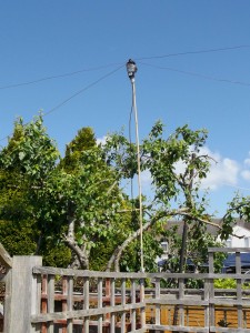
Fan Dipole Centre

Fan Dipole Centre Support

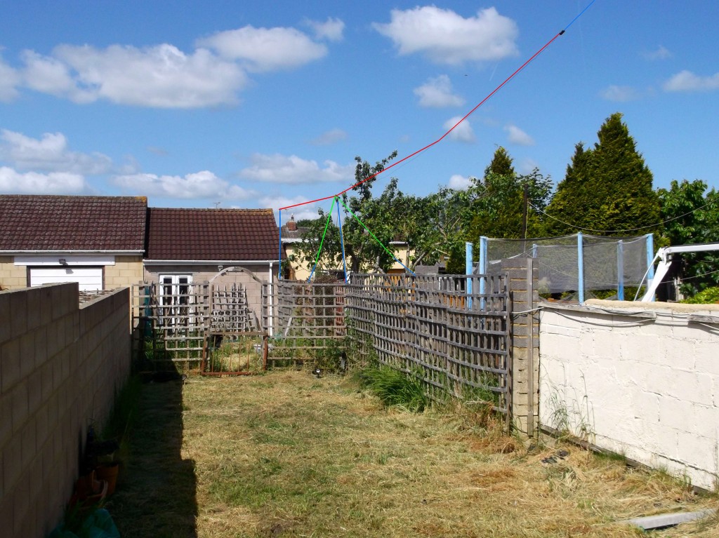
I sometimes have trouble explaining just how simple the antenna is on air, so thought I’d post some photos here.  The fan dipole now consists of 40m (horizontal) and 17m (inverted V) elements, supported at the centre and far end by 9ft bamboo canes; The near end is supported via fishing line to an upstairs window.  I used a low loss coax feed (aircell 5) from shack to dipole centre, which feeds the elements (solid copper) via Comet CBL-1000 (click for review).

Total height at peak is aprox 5m (16ft?), so practically NVIS; fantastic for inter-G but useless for DX due to the high angle of radiation.  Reports on both bands are very good indeed.  You can’t beat resonant antennas!  Obviously no ATU needed, although an ATU can be used to operate on 15m (21MHz) and possibly 6m (50MHz) which are the odd multiples of 7/18MHz.

Fan Dipole Highlighted

Fan dipole. Red = 40m elements, Green = 17m elements, Blue = Supports. CLICK TO ZOOM

Despite using bamboo canes which will need regular replacement, the antenna has now been up 6 months without issues, surviving several storms.  The bamboo canes, copper wire and fishing line blend in with the environment so are hard to spot; very neighbour friendly!

Update: The fan dipole has now been up over a year with no bamboo casualties, even surviving the storms.

Posted in Uncategorized | Tagged , , , , | Leave a comment

Simple & Cheap Speaker Upgrade

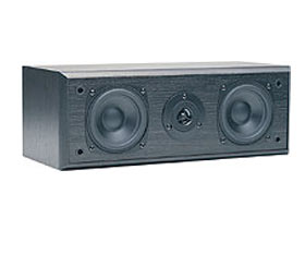
centre10-mon

The Gale Centre Speaker

This will be a very brief post but I thought it too good not to share.  For some time now I’ve had my FT847 in a less than ideal position meaning I’ve either had muffled audio from the internal speaker or poor/thin audio from a cheap external ‘CB’ type speaker.

Many years ago I tried using a standard hifi speaker for communications but found the frequency response to be less than ideal for voice; boomy bass and great treble but an apparent total lack of mid range ‘voice’ frequency.

Recently, I was given a cheap (when new, even cheaper to me being free!) Gale centre speaker from an old surround sound setup.  It took a couple of days of this speaker sat on a shelf before the brain gears started whirring.  A centre speaker is *designed* for speech, it’s job is to make vocal passages stand out in amongst the booming noise of the other 4 speakers and ground shaking sub.

5 Minutes later, a 3.5mm jack soldered to a cable and the difference is incredible.  This is being driven directly from the 847 output with no external amplifier.  The output is incredibly crisp with plenty of clarity-giving mid range, whilst also having the wider frequency response for that ‘BBC’ broadcast sound.  It’s fantastic – don’t throw that old centre speaker away, it’s probably just as good (if not better) than an expensive dedicated communications speaker!

Posted in Uncategorized | Tagged , , | 1 Comment

Upgrade: Yaesu MH-31 to Studio Mic

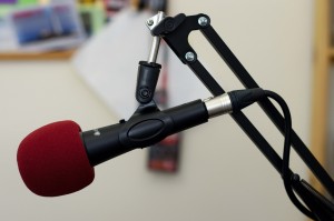
mic_mounted

The Chord Mic, Desk Mount and Foam Pop Shield

Some time ago I started receiving reports that the audio on my FT847 was very narrow. After much investigation and eventually swapping mics with my FT817 I realised it was the mic that was faulty. Oddly, swapping the mic element for another also failed to rectify the problem; the capacitor, resistor and switch in the mic tone control all checked out OK too.

With none of the above making much sense I decided to use the FT817 mic as a temporary solution whilst considering long term upgrades.  I thought of this as an opportunity to upgrade to outboard gear; a decent mic, preamp, compressor, gate and possibly EQ. However, after reviewing my options, the cost and possible problems converting line level output back down to mic level – I decided I should perhaps start with the basics.

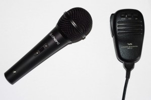
mics

Chord vs Yaesu

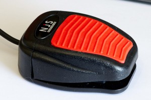
I ordered a cheap Chord ‘karaoke’ microphone (£10), desk stand (£10) and foam pop shield (£1) from eBay.  I then added a discounted latching foot switch from Maplin (reduced to £10) and wired some 1/4 jack sockets to the FT847 mic connector; one for the mic, one for the PTT.

Initial reports have been positive, although testing TX audio via Hack Green I think I may need some carrier adjustment. The Yaesu MH-31 does sound quite narrow whereas the studio mic audio has significantly more bass. Personally, whilst I agree the studio mic sounds ‘better’, some carrier adjustment would likely reduce the bass and reach a happy balance between fidelity and clarity.

footswitch

The Maplin Footswitch / PTT

In summary, for ~£30, a very worthwhile investment. Plus, it means the working MH-31 can be returned to my FT817!

I’ll attempt to record some samples of the audio from both microphones once I have the carrier adjusted to the optimum level for both mics.

Update: I’ve been running with this setup for several months now and continue to get unsolicited fantastic audio reports.

Posted in Uncategorized | Tagged , , , , , , , , | 3 Comments

Pixie CW Transceiver

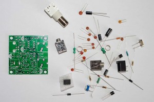
Here’s a quick review of the Pixie CW Transceiver, built for 40m.  I ordered two identical kits from China via ebay, one for myself and another for a friend.  The kits arrived and appeared to be well put together;  the PCB (5cm sq) seemed of a good quality with clear printing and the components (even a dummy load resistor) were supplied in individual bags.

pixie1

The Pixie Kit

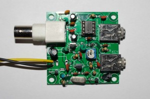
The Pixie took approximately 45 minutes to assemble.  During this time I noticed some pads were reluctant to hold solder. I’m unsure why this was – visually they looked great, but solder just wouldn’t flow and ‘bond’ in a satisfactory manner.  I haven’t seen others mention this issue so perhaps it’s my fault for not cleaning the PCB first.

Once assembled, I connected a speaker and CW key, applied 12V and … nothing. I could see some minimal current being drawn on the PSU so disconnected the speaker and attached some headphones.  Success!  It seems the LM386N isn’t up to the job of driving a small loudspeaker but it’s more than happy with headphones.

img_0001

The Assembled Pixie

Attaching the Pixie to my 40m dipole I could hear several very clear CW transmissions.  Of course, without filters on a busy band – this could be a problem. Still, I hit the key and monitored my transmission on the FT847;  current draw increased on TX and a clear tone was heard on the 847.  Plus, an added bonus – despite learning and practising on a paddle key, I managed to send some CQs with good (IMO!) timing on a straight key.

Future plans:-

1. Measure power output
2. Hold an actual QSO!
3. Mount the Pixie in an enclosure (with 9V battery?)
4. Order and build a ‘Frog’

In summary, well worth the money.  I not only enjoyed the construction (despite the problem pads!) but have a working CW XCVR 🙂

Posted in Uncategorized | Tagged , , , | 7 Comments

Review: Atom 40S Mobile Antenna

My previous experiences with HF mobile antennas have not been so great.  On a previous car a pro-am/hamstick mounted on the boot required bonding of the boot to car body with copper in order to ensure a good enough ‘ground’; removing paint and welding copper braid to metal on a nearly-new Mercedes was not my idea of fun (but of course, radio wins – so I did it regardless!).

Atom 40S - Image from Moonraker

Atom 40S – Image from Moonraker

On my current vehicle I decided to use a mag mount.  Only, the 40m ham-stick I already had caused too much wind resistance, resulting in the mag mount becoming a missile with an unhealthy attraction to the rear window when travelling over 30mph.

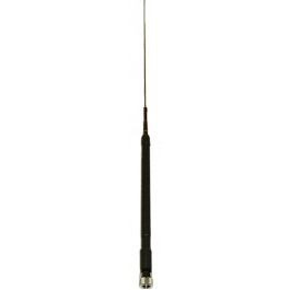
In order to add further compromise to an already compromised solution, I ordered an Atom 40S from Moonraker.  This was the only ‘shortened’ 40m mobile antenna I could find.  Due to the short length (1.6m?) and base loading I wasn’t expecting much more than a dummy load on 40m.

The result?  Whilst mobile on my commute between Swindon and Knutsford (20m South of Manchester) I had constant QSOs on 40m.  I joined a net on 7.180 and talked the entire journey with great reports both ways from all stations.  Sure, I expect I was an S point down compared to my hamstick which itself is probably a couple (or more?) S points down in comparison to a full size antenna.  However, with 100W from an Icom 706 (possibly at a guess 10W ERP after antenna losses?) I wasn’t struggling to make contacts.

As the band closed to inter-G I finished the journey with QSOs into the Netherlands, also with great reports.

Due to the shortened size of the Atom 40S the SWR does climb steeply either side of the resonant frequency. I adjusted for 7.15 MHz and find it usable (SWR < 2:1) between 7.1 and 7.2 MHz.

Overall, I’m impressed.  My only criticism would be the grub screws which appear to be made from butter.  From the factory one loosened without issue.  The other required substantial swearing, application of heat (discolouring the chrome as a result) and several attempts at packing the grub screw with foil in order to gain any sort of grip on the now rounded cavity.  If this wasn’t a bank holiday weekend I’d have probably just called Moonraker and asked for a replacement!

The specifications from Moonraker are as follows:-

Type: Base loaded HF mobile antenna
Frequency: 7 MHz
Length: 155cm (whip only 48″)
VSWR: 1.5:1 or better
Power: 200 watts
Fitting: PL259 type
Bandwidth: 60kHz

I’m not linked with Moonraker in any way but a (mostly) happy customer.  The Atom 40S far exceeded my expectations and for < £30 has given me the ability to operate mobile on 40m.

I hope to perform some a/b tests between the Atom 40S and a traditional pro-am/hamstick.  This post will later be updated with results.

Posted in Uncategorized | Tagged , , , , , | 2 Comments

Alternative, Portable or Mobile?

The UK licence conditions seem fairly clear when it comes to the definitions of mobile and portable; however on deeper analysis it’s clear some degree of interpretation is needed. Following a recent heated (to put it mildly) debate on the dreaded Facebook, I thought this was a great opportunity to put my thoughts down in the form of a blog post.

M0SPN Portable

M0SPN: Portable or mobile?

Firstly, identification of portable (/p), mobile (/m) and alternative (/a) are now optional.  However, when used, I believe we should use these in a consistent manner.  From the Facebook discussion it was also obvious many amateurs have been using these terms incorrectly for years and were now passing on their misunderstandings to newly licensed operators.

Firstly, the current license states the following:-

portable1


Note point 2: “Mobile means Radio Equipment is located … on the person … where the Licensee is a pedestrian”.

Given the definition of Mobile, the licence then explains:-

portable2

It is clear that the long held belief (by some) that /p refers to ‘pedestrian mobile’ or use of ‘portable radios’ is incorrect.  The older BR68 also contains similar wording;  this is not a recent change * (note: see update below).

If a licensee is operating from an alternative (registered) address he/she signs /a (alternative). If a licensee is operating whilst mobile (in a vehicle OR on foot) he/she signs /m (mobile). If a licensee operates at a temporary location, he/she signs /p (portable).

Simple, right?  Only, apparently it’s not.  “So I’m mobile in a car, but what if I stop?” and “SOTA operations sign as portable even when using radios in backpacks, transported on foot”.

If you’re stationary with no plans to move whilst transmitting (for example parked up on a hill for the afternoon, or activating SOTA) then sign portable.  If you have an intention to move whilst transmitting (in a vehicle or on foot) then sign mobile.

Update: G8ADD via MM0HAI’s blog states:-

"I have my first licence issued in 1964 put away so safely that I
 can't find it! This is from a re-issue in 1977:

9.(1)(b) at the temporary premises the suffix "/A" shall be added
 to the callsign.
9.(1)(c) at the temporary location or as a pedestrian the suffix
"/P" shall be added to the callsign.
9.(1)(d) in or on a vehicle or vessel the suffix "/M" shall be 
added to the callsign.
9.(4) When the station is used at the temporary premises or 
location, the address of the temporary premises or location shall
be sent at the beginning and end of the establishment of 
communication with each separate amateur station, or at intervals
of 15 minutes, whichever is more frequent."

This is clearly where the confusion can be found.  Does anyone know when these definitions were changed to reflect the modern usage?

Further update, Trevor M5AKA (via twitter):-

portable3


“I believe the removal of pedestrian from /P was in the … Edinburgh Gazette Issue 22479 30 December 1988” – Trevor M5AKA (click link to open, see page 1933 / page 11 of pdf)

Any further comments?  If so I’d love to hear from you!

Posted in Uncategorized | Tagged , , , | 5 Comments

Unexpected QRP Success

A few QRP CQ calls this afternoon on 40m resulted in a nice mini pile-up!  Running 5W from the FT847 to the 40m garden dipole, the first station to respond was F5BDK (Mario, near Paris). This was quickly followed by G8RZ, GW8TIX, G6NYG, G4DFI, G4BSS, 2E0FUR, M3LDS, G3EPH, G3LGL and finally MM6LDC. Conditions certainly favoured QRP today with great reports all round.  Many thanks to all who took the time to respond to my call.

Posted in Uncategorized | Tagged | Leave a comment

Random Wire Loop Antenna

I’ve recently been researching multi band antennas. My first thought was to remove the balun from my 40m dipole, feed with ladder line from an external auto-ATU and treat as a doublet. However, in several auto ATU manuals one antenna kept being mentioned: the loop (often a delta loop).

Many documents refer to dimension calculations for a single band of operation. Others state dimensions but are vague about how these calculation are made whilst also referring to use over multiple bands. I couldn’t find much regarding feeding of random loops.

random-wire-loop-m0spn

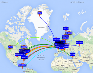
20W 80/20m WSPR Map

In a spare 30 minutes I thought I’d string up the largest loop I could fit in the garden. What’s the worse that could happen?

The resultant loop was approximately 70m in length and strung up in a horizontal sloping rectangle, loop ends entering the upstairs shack window and fed directly from an old KW ATU using balanced outputs. The wire used was very thin, solid core ‘bell wire’; far from ideal for an antenna.

The ATU tuned most bands but on TX I noticed a brief arc on a speech peak. I had a 4:1 balun I’d previously made for another project so placed this between the ATU and loop.  The loop then presented a much easier load and tuned without issue on every band I tried (80m to 10m).

Later in the evening I performed some WSPR tests using 20W output on both 80 and 20m. The results are show above (East was predominantly 80m, West 20m)

On RX, comparing the loop and 40m resonant dipole, a 2 S point (~6dB) difference was observed in favour of the dipole.

However, in summary, surprisingly good performance for a loop made of unsuitable wire and thrown up with no thought for dimensions. More investigation and experimentation definitely required!

Posted in Uncategorized | Tagged , , , , | 3 Comments

FT817 Chinese TCXO and Collins 2.3 kHz SSB Filter

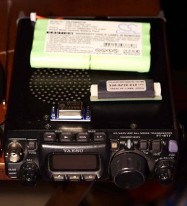
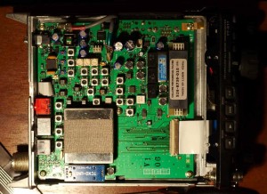
FT817_M0SPNOperating on the crowded 40m band has made me appreciate the need for good filters. I’d read many comments regarding filter brands and bandwidths, plus viewed several videos that show an FT817 with collins filter fitted and the author stating “no difference in receive audio – waste of money”. I’m not sure what people expected here as there were no adjacent signals to reject!

I decided to order the Yaesu Collins YF-122S (2.3 kHz) as a) it’s the standard option and b) I’d read reports that 2 kHz was too narrow. I also ordered a Chinese TCXO (£10) as I figured for that money it would be daft not to – plus whilst operating on the FT817 I may as well do both upgrades.

The first thing I noticed when switching the Collins filter in circuit was a slight increase in RX signal level. I then tuned around the band, found some strong signals and tuned to the signal edges whilst switching the filter in/out. Initial impressions were poor; no noticable improvement. However, I then discovered at the very extreme edges (nearing 3kHz off unwanted signal) the interfering signal was completely removed. The high pitch squawking of an adjacent signal became completely rejected with the filter switched inline.

FT817b_M0SPNHowever, in practice, with the trend for ‘hifi’ sounding wide signals, I question the usefulness of this. In hindsight a 2kHz INRAD would have likely been a much better investment.

Switching to TX, I understood the flat frequency response within the pass band gave punchier audio. Keen to try this, I connected my 817 to my 40m dipole, started Hack Green SDR receiver on my PC and made a couple of test transmissions. This is highly unscientific as it assumes I spoke at the same volume, the same distance from the mic. However, I tried this several times and reproduced the same results; an increase in transmitted signal/audio roughly equal to the increase I’d noticed on RX when switching the filter inline.

An a/b comparison recorded via Hack Green SDR can be found here. Keep in mind this was recorded using just 5W from my home, signal strength was not great.

In summary, I’d say the filter was probably worthwhile purely for the marginal signal improvement (both RX and TX).  I’m unsure if this is due to the frequency response or less insertion loss compared to the standard ceramic filter.  In terms of filter bandwidth and performance per £ I believe a 2 kHz SSB INRAD filter would have been a much better investment.

The TXCO? I had never noticed an issue with frequency stability before (to date I’ve operated primarily on HF). However, the replacement works without issue and reports online suggest it’s as stable as the official TCXO. This could be a worthwhile upgrade when operating portable on 2/70 UKACs in the future.

Posted in Uncategorized | Tagged , , , , , | Leave a comment

G6LVB (LVB) Tracker

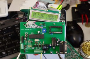
LVB_Track_M0SPN

Assembled G6LVB Tracker

This has been a long running project.  I bought the LVB Tracker kit (inc LCD display) probably a year ago and construction took place over a rainy weekend. However, programming the PIC has not been so simple.

Importing the provided .hex file into either the MPLab IDE or a standalone programmer (programming via both a socketed hardware programmer and ICSD) resulted in various warnings about configuration bits not being set.  The author hints in the instructions that the provided programmer binary has some intelligence and does more than just write the data. He also states the programmer is Windows only and must use a real serial port (not a USB->RS232 converter).

The problem for me was a) all my machines run Linux and b) my only machine with a real serial port is used as my ‘radio’ machine, is in an awkward location and runs completely headless (no monitor or keyboard).  I really didn’t like the idea of digging the machine out, swapping HDs and installing Windows.  So, the project stalled for almost a year.

Today I dug an old machine out of the garage.  Replaced a failed motherboard, installed XP, fought with a million drivers and hooked up a serial cable between the serial port and the LVB Tracker.

PicProg firmware.hex \\.\COM1

The programmer indicated it had detected the PIC and selected a programming method suitable (I suspect setting the relevant config bits).  Success!

Only, the LCD display now seemed to be randomly garbled.  30 minutes later and a poor joint on the LCD ribbon cable was identified.  Issue fixed and the LVB Tracker lives!

Maintenance could however be an issue.  The author states:

“The firmware is written entirely in Knusden Data’s C. This was chosen primarily because of its integrated floating point library.”

I see Knusden C is still available, however my preference going forward would be to port the source to the MPLab C compiler (assuming floating point is available).

The original .hex file and a dumped .hex file (once programmed, with full configuration bits etc set) can be found below.  The dumped .hex should be complete but I haven’t yet re-flashed this to confirm (since tested/confirmed OK by ON7CFZ, many thanks!).

Original: LVBTrack.hex

Dumped 16F876 post programming (by custom programmer): LVBTrack_Dumped.hex

The next task will be to mount the tracker in a case, add push buttons and connect my Yaesu G-5500 controller to test.  I do still have issues controlling the FT847 in satellite mode using CAT (poor support in Hamlib) but at least one part of the puzzle is almost complete.

Posted in Uncategorized | Tagged , , , , , | 3 Comments